9.4 DESIGN OF BRAZED JOINTS FOR ROCKET ENGINES
The best tube fitting or gasketed flange joint falls short of a good welded or brazed joint in reliability. Hence, every sealed joint on each rocket engine should be studied aiming at its elimination, or its replacement by a hermetically sealed joint, for increased overall system reliability. Specifically, certain sealed joints originally provided for convenience during the development phase of an engine system may no longer be needed as development approaches completion.
The brazed joint design shown in figure 9-16 may be utilized effectively to replace tube fittings and flange joints. A union sleeve with internal recesses for preplaced braze alloy foils connects the tube ends. The brazing can be accomplished by induction-heating coils, either in-place on the engine, or on the bench. Coax cables with low impedance losses have been developed, permitting a brazing fixture to be used in-place, even at great distances from the generator.
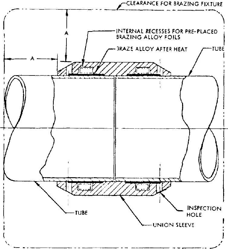 Figure 9-16.-Typical brazed joint design.
Pertinent design consideration and details of brazed joints for rocket engines are as follows:
Working Fluids, Pressures, and Temperatures Applicable to Brazed Joints
There are virtually no design limitations on the types of fluids that can be handled by brazed joints. Chemically active propellants such as fluorine, hydrazine, etc., have posed no problems to brazed joints. Similar satisfactory results have been obtained with brazed joints used in liquid hydrogen, liquid oxygen, hydraulic, and pneumatic lines.
Structurally, brazed joints are designed to be as strong as the strongest tubing or duct of like material. Brazed joints have demonstrated reliability at working fluid pressures as high as 4000 to 5000 psi . Generally, brazed joints are recommended to be limited to service temperatures of less than . Allowance must be made for strength degradation of brazed joints used at elevated temperatures.
A typical brazed joint is illustrated in figure . The union sleeve can be used to join tube to tubes, tube to bellows, or tube to components. Line sizes as large as 6 inches (inside diameter) and walls as thin as 0.005 inch have been successfully induction brazed. Tubes and sleeves for brazed joints can be made of aluminum alloys, austenitic and semiaustenitic steels, and nickel-base alloys such as Monel.
A preplaced braze alloy in the form of 0.001 to 0.003 -inch-thick foil is snapped into recesses inside of the union sleeve. Diametrical clearances of inch between sleeve and tubing are found to give satisfactory results. Holes are provided on the sleeve to permit visual joint inspection after brazing. The quality of the brazed joint can be also judged by the degree of external braze-alloy filleting at the outer edges of the sleeve. The recesses for the braze alloy are located midway between tube and sleeve ends. The length of the union sleeve can be determined by the braze bond shear strength and the effective bond area. Sleeve lengths range from 0.5 to 2 times the tube outside diameter.
Many types of brazing alloys can be used. A eutectic alloy of composition 71.8 percent silver, 28 percent copper, and 0.2 percent lithium, with a melting point of , can braze without flux and permit in-place brazing.
System Applications of Brazed Joints
After an engine system has reached its production phase, the majority of the small- or medium-size sealed fittings and flange joints should be replaced by well-located brazed joints. These should be designed to facilitate in-place brazing, if possible. This requires a specific clearance around the joint for the brazing fixture. The minimum clearance for the brazing fixture (fig. 9-16) is inch for tube diameters of to inch; inch for a -inch diameter; inch for a -inch diameter; and 1 inch for 1 - to -inch diameters. For repair of lines or servicing of components with brazed joints, a length of line may be cut out and a new length inserted and brazed in-place, with two union sleeves.
Figure 9-17 presents the in-place brazed joints applied to an upper stage propulsion system. About 80 percent of the original fittings and flanged joints were replaced by brazed joints, which eliminate considerable weight. In addition, it also permits the use of high-strength, thin-wall tubing, instead of the older heavy-wall tubing.
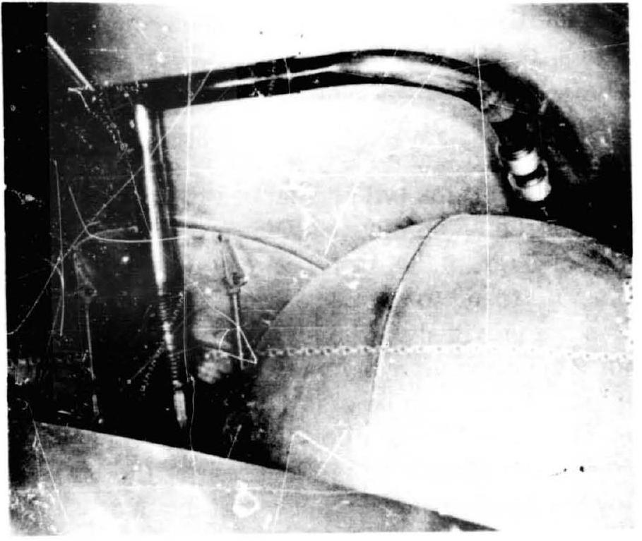 Figure 9-17.-In-place brazed joints applied in an upper stage propulsion system.